DICOM SEG Segmentation Viewer
Labelled regions carried beside their source images
DICOM Segmentation (SEG) stores pixel-based labels — anatomical structures, lesions, organs at risk — as a separate object that references a source image series. It is the standard delivery format for AI segmentation frameworks, but also for manual or semi-automatic contouring tools.
Weasis displays SEG regions as a colored overlay on the source images, with independent visibility and opacity control per region — available since v4.3.0, and substantially extended since v4.7.0 with:
- Overlays in MPR and 3D Volume Renderer views, in addition to the standard 2D viewer.
- Simultaneous display of all SEG files linked to the current series, each toggleable independently.
- Support for the FRACTIONAL (probability / occupancy maps) and LABELMAP (multi-segment files used by tools like highdicom) segmentation types produced by modern AI frameworks.
- The same smooth fractional overlay reused for RT Dose isodose rendering — see the RT tutorial.
Extended again since v4.7.2 with:
- Show all / Hide all buttons in the Segmentation panel, and the Alt + S shortcut to toggle every segmentation of the selected view at once.
- Segmentations that are rarely diagnostic (table, couch, patient support…) hidden when loaded — the keyword list is configurable, and an option hides every segmentation until you enable it.
- A color swatch in front of each node of the region tree (also in the RT tool), and a tooltip on every node.
- A complete listing: every SEG that can be overlaid on the displayed series is shown, including SEG files that reference another series sharing the same frame of reference.
- Several SEG files rendered together in 3D (merged into a single volume) and two new mask modes that cut the volume rendering with the segmentation.
- A Loading segmentations… message painted in the views while a segmentation volume is built in the background.
How to display DICOM SEG in the 2D viewer
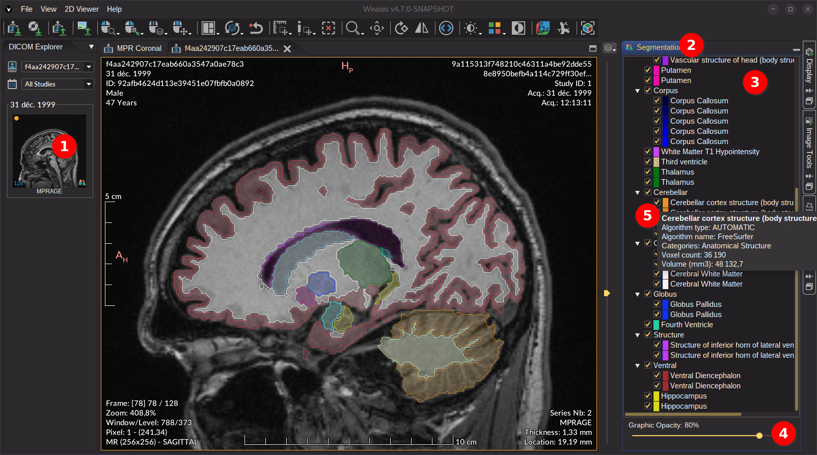
To display the SEG regions as an overlay on the image, follow these steps (see the image below):
- Open a DICOM series that has a linked SEG object. The link is indicated by the segmentation icon in the lower-right corner of the thumbnail. A series without the icon may still display the segmentation — see which series can display a segmentation.
- Once the image is displayed, click on the vertical button to open the Segmentation panel on the right side of the viewer.
- Every SEG file that can be overlaid on the current series appears as a top-level node in the tree. Expand a SEG node to reveal its regions and tick the ones you want to display. Each node carries the color used to draw it. Regions that share a common name prefix are grouped under a parent node — the parent must be checked for any of its children to be visible.
- InfoOptional Adjust the global graphic opacity (border and interior fill) with the slider.
- InfoOptional Use Show all / Hide all at the bottom of the panel to tick or untick every segmentation in one click. Alt + S does the same directly from the view without opening the panel since v4.7.2: it hides every segmentation when at least one is visible, and shows them all otherwise.
- InfoOptional Use tooltips to see the region description, voxel count and estimated volume for each region. For FRACTIONAL regions a color-gradient bar is also displayed to help interpret the probability ramp.
Try to open a SEG sample
Right-click on a region in the tree to access:
- Select / unselect all child nodes (parent only) — toggle visibility for every child region at once.
- Fill opacity — transparency of a region’s interior relative to its border.
- Default: 20 %
- Perceived opacity = Line opacity × Fill opacity
- Example: 80 % line + 20 % fill → 16 % perceived interior opacity.
- Show in the image view (leaf only) — jumps to the slice where the region has its largest cross-section. It also works in MPR since v4.7.2, where the crosshair is moved to the centre of the densest slice of the region; the search runs in the background with a progress bar shown in the views (Locating the region…).
- Pixel statistics from the selected view (leaf only) — computes statistical descriptors of pixel values inside the region. For the parameter definitions, see Pixel Statistics.
Loading a DICOM SEG. The first time a SEG is shown — in the 2D viewer, MPR or 3D — Weasis decodes it in the background. Scrolling and other interactions remain responsive while decoding runs; the regions appear as soon as the SEG is ready.
A cancelable progress entry is shown at the bottom of the DICOM Explorer, so a large or slow SEG can be canceled without blocking the rest of your work. The views themselves also display a Loading segmentations… message while the build is running since v4.7.2, so it is clear that the missing overlay is only pending.
Once decoded, the SEG is shared between the 2D, MPR and 3D views — loaded only once even with several views open. Weasis may release it automatically when memory gets tight and reload it on demand the next time it is needed.
Which series can display a segmentation?
A SEG object declares the images it was drawn on in its Referenced Series Sequence (or, frame by frame, in its Derivation Image Sequence). Those directly referenced series are the ones decorated in the DICOM Explorer with the segmentation icon in the lower-right corner of the thumbnail.
That icon marks a declared reference — it is not the complete list of series the overlay can be drawn on. A SEG is also offered since v4.7.2 on any other series of the same patient that shares its Frame of Reference UID, even though that series carries no icon. Both objects then live in the same 3D patient coordinate system, so the segmentation masks can be placed on the images by spatial position instead of by SOP Instance UID.
| Thumbnail | Relation to the SEG | What you get when the series is opened |
|---|---|---|
| With the icon | The SEG explicitly references this series. | The SEG is listed in the Segmentation panel and the regions are drawn on the referenced images. |
| Without the icon, same Frame of Reference UID | No declared reference, but the same patient coordinate system. | The SEG is still listed in the Segmentation panel, and the regions are drawn on the images whose spatial position matches a segmentation frame. |
| Without the icon, different (or missing) Frame of Reference UID | Unrelated geometry. | The SEG is not proposed — there is no reliable way to position the masks. |
This is what makes it possible, for example, to display a segmentation computed on a contrast phase over another phase of the same acquisition, or over a series reconstructed with a different kernel, slice thickness or resolution: only the geometry has to match, not the SOP Instance UIDs. Weasis reslices the segmentation volume when the image plane is not parallel to the segmentation frames.
When a SEG carries no usable reference at all — frequent with AI-generated objects — Weasis links it to every image series of the patient that shares its Frame of Reference UID, and those series do get the icon. The icon is therefore missing only when the SEG references another series explicitly.
Segmentations hidden by default
A SEG file can be loaded but not displayed since v4.7.2: it still appears — unticked — in the Segmentation panel and can be shown at any time. This avoids cluttering the image with segments produced by acquisition or planning tools that are rarely of diagnostic interest — the table, the couch or the patient support.
These settings have a page of their own since v4.7.3, File > Preferences > Viewer > Segmentation (they were under 2D Viewer before), because they govern every view that draws a SEG — 2D, MPR and 3D. A third rule has been added for studies that carry many segmentations at once. Any one of the three rules is enough to hide a segmentation:
| Setting | Behavior |
|---|---|
| Hide all segmentations by default | Hides every segmentation on load — nothing is drawn until you enable it in the panel or with Alt + S. It overrides the two rules below, which are greyed out while it is checked. |
| Keywords to hide | Comma-separated keywords. A SEG file is hidden when one of them appears in its Series Description, Content Description or Content Label, or when every one of its segments matches by label, description or algorithm name — so a multi-segment object is not hidden just because one of its segments happens to be the table. Case, spaces, underscores and hyphens are ignored when matching. Default: table removal, table segmentation, tabletop, couch, patient support, bed removal. An empty value disables the rule. |
| Hide from since v4.7.3 | Number of segmentations loaded for the patient from which they all start hidden, exactly as Hide all does — beyond a handful they paint over each other and none of them is readable. Segmentations already hidden by the keywords are not counted, so a study whose only extra objects are table removals is not considered crowded. Default: 3. Enter 0 to disable the rule. |
The count spans the patient, not the series: a cardiac study routinely spreads its segmentations over several series, and counting each series separately would leave the single-file ones showing while the crowded ones hide.
Hiding is only a default. A hidden segmentation is fully loaded and listed unticked in the Segmentation panel — tick it, or press Alt + S, to display it. Changing these settings also re-applies them to the segmentations already loaded since v4.7.3, at the next repaint, instead of only to the next study; the ones you ticked by hand keep their state. The Restore default values button of the page puts the three settings back to the values above.
The same values can be pre-set at the server side with the preferences weasis.dicom.seg.hide.all, weasis.dicom.seg.hide.keywords and weasis.dicom.seg.hide.count.
Supported segmentation types
Weasis supports all three DICOM SEG segmentation types:
| Type | What it represents | How Weasis displays it |
|---|---|---|
| BINARY | Each pixel is either inside or outside the segment. | Colored contour drawn on the image. |
| FRACTIONAL — PROBABILITY | Each pixel carries a value between 0 and 1 expressing how confident the AI is that the pixel belongs to the segment. | Smooth colored overlay: more transparent where confidence is low, more opaque where it is high. The opacity slider scales the whole gradient. |
| FRACTIONAL — OCCUPANCY | Each pixel carries a value between 0 and 1 expressing how much of the pixel is actually covered by the segment (partial-volume fraction). | Same smooth overlay as PROBABILITY — only the meaning of the value differs. |
| LABELMAP | Several segments are packed into a single image, with the pixel value identifying which segment it belongs to. | Each segment is extracted automatically and drawn with its own color. |
Some AI frameworks export FRACTIONAL segmentations without an explicit reference back to the source series. Weasis matches them to the correct images automatically, via the DICOM frame of reference — see which series can display a segmentation.
Segmentation overlay in MPR
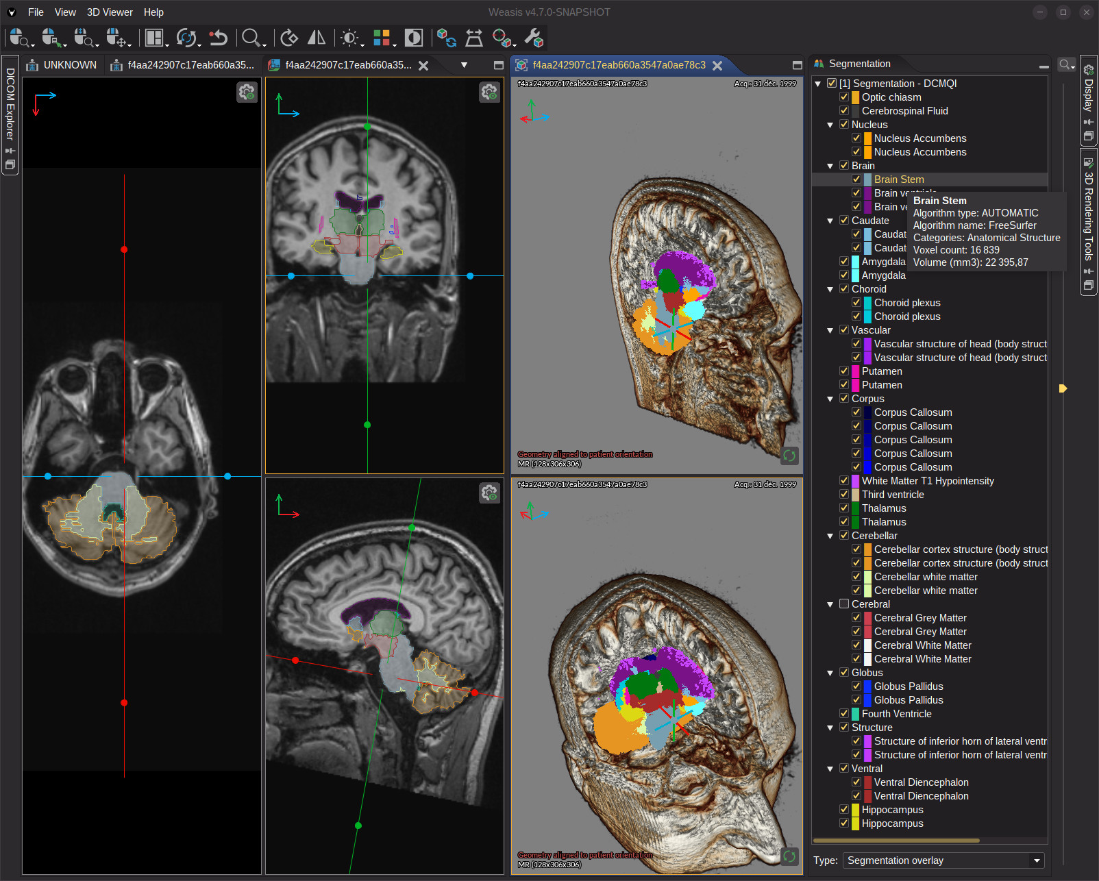
When a DICOM SEG is linked to the current series, the overlay is automatically available in the Multi-Planar Reconstruction (MPR) view. The same Segmentation panel controls visibility and opacity for all three planes (axial, coronal, sagittal — plus any oblique cut) at once.
For MPR, Weasis additionally has to reslice the SEG along the new planes. This extra step runs in the background; the overlay appears on every plane as soon as it completes.
The MPR overlay works even when the SEG has a different orientation, spacing or scanning direction than the source images — for example an AI model that segments at a coarser resolution. Weasis reprojects the mask into the image coordinate system, so contours stay aligned on every plane.
Segmentation overlay in the 3D Volume Renderer
The 3D Volume Renderer offers five segmentation modes, selectable from the Segmentation panel (the two mask modes since v4.7.2):
| Mode | What it shows |
|---|---|
| No segmentation | Volume rendering only — no overlay. |
| Segmentation only | Only the labeled regions are rendered; the anatomy is hidden. Useful to review the AI output on its own. |
| Segmentation overlay | Regions are drawn on top of the volume rendering, with the anatomy remaining visible beneath. |
| Mask (voxels inside segmentation) | The segmentation is used as a cutting mask: only the original voxels located inside the visible regions are rendered, with their normal volume rendering. Isolates an organ or a lesion with its real densities instead of a flat color. |
| Mask (voxels outside segmentation) | The opposite: the voxels inside the visible regions are removed from the rendering. Handy to take out an implant, the table or a contrast-filled structure that hides the anatomy behind it. |
A few things to keep in mind when working with the 3D overlay:
- Toggling a segment is instant. Visibility, color and opacity changes update the 3D view immediately, even on very large volumes — Weasis only refreshes the color table, not the segmentation itself.
- Overlapping segments are handled cleanly. When two segments share the same area, their colors are blended automatically; you do not have to pick which one wins.
- 2D, MPR and 3D stay in sync. Showing or hiding a segment in the panel updates all three views simultaneously.
- Several SEG files at once since v4.7.2. Every SEG file linked to the series is resampled on the image grid and merged into a single segmentation volume, so segments coming from different files are rendered together. Building this volume runs in the background — a progress bar is displayed in the view — and Show all / Hide all are available in the 3D Segmentation panel too.
- Segments are lit like the anatomy since v4.7.3. The Shading option of the Volume Rendering panel also applies to the segmentation surfaces.