DICOM 3D Viewer: Volume Rendering
Rotate, slice, recolor and light a volume
The 3D viewer reconstructs a CT, MR, PET, or other volumetric series into an interactive volume rendering that can be rotated, sliced, recolored, and lit in real time. Typical uses include reviewing CT angiography, inspecting bone or vascular anatomy, surgical-planning views, and quickly conveying findings to colleagues or patients. The viewer is available since v4.1.0; its renderer and view synchronization were substantially improved since v4.7.0.
Internally, the volume is rendered on the graphics card using a ray-casting algorithm implemented in GLSL shaders, so a modern GPU is required (see Requirements) but no extra installation step is necessary.
Requirements
The graphics-card capabilities used by Weasis are reported under OpenGL Support in File > Preferences > Viewer > 3D Viewer:
- Driver version — requires OpenGL 3.3+ since v4.7.0. Two rendering backends are used depending on the available OpenGL version:
- OpenGL 4.3+ — uses a Compute Shader for optimal performance.
- OpenGL 3.3 – 4.2 — uses an FBO-based Fragment Shader fallback (fully functional, but may be less performant than the Compute Shader path). macOS is capped at OpenGL 4.1 and therefore always uses this path. This path renders at a reduced resolution while the view is being dragged since v4.7.3 — see rendering during interaction.
- Max 3D texture dimension length — the upper limit, in voxels, of any X / Y / Z dimension of the volume.
- Any other entry shown in red indicates a non-optimal configuration. The viewer often still works — see how to limit the size of 3D textures if performance becomes an issue.
Use the high-performance graphics card on a Windows laptop
The card in use is shown on the Graphic card line under OpenGL Support. To switch to the dedicated card:
- Close Weasis.
- Open Settings > System > Display > Graphics.
- Click Add desktop app and select
C:\Program Files\Weasis\Weasis.exe. - Click Weasis in the list and set GPU preference to High performance.
- Start Weasis again.
If the integrated card is still shown, use NVIDIA Control Panel > Manage 3D settings > Program Settings (or the equivalent in AMD Software) for Weasis.exe.
Open the 3D viewer
Open the viewer by clicking in the toolbar of a series view, by double-clicking the series thumbnail, or by right-clicking the thumbnail in the DICOM Explorer and choosing the 3D viewer.
If the series is a multi-phase 4D acquisition (e.g. a cardiac CT with several temporal phases), Weasis automatically splits it into individual phase sub-series when 2–7 phases are detected. For series with 8 or more phases, a confirmation dialog is shown first. Open any resulting phase sub-series to render it in the 3D viewer. See 4D Series Sub-Series Splitting for details.
Try it on a volume dataset (Medical Demos from data.kitware.com)
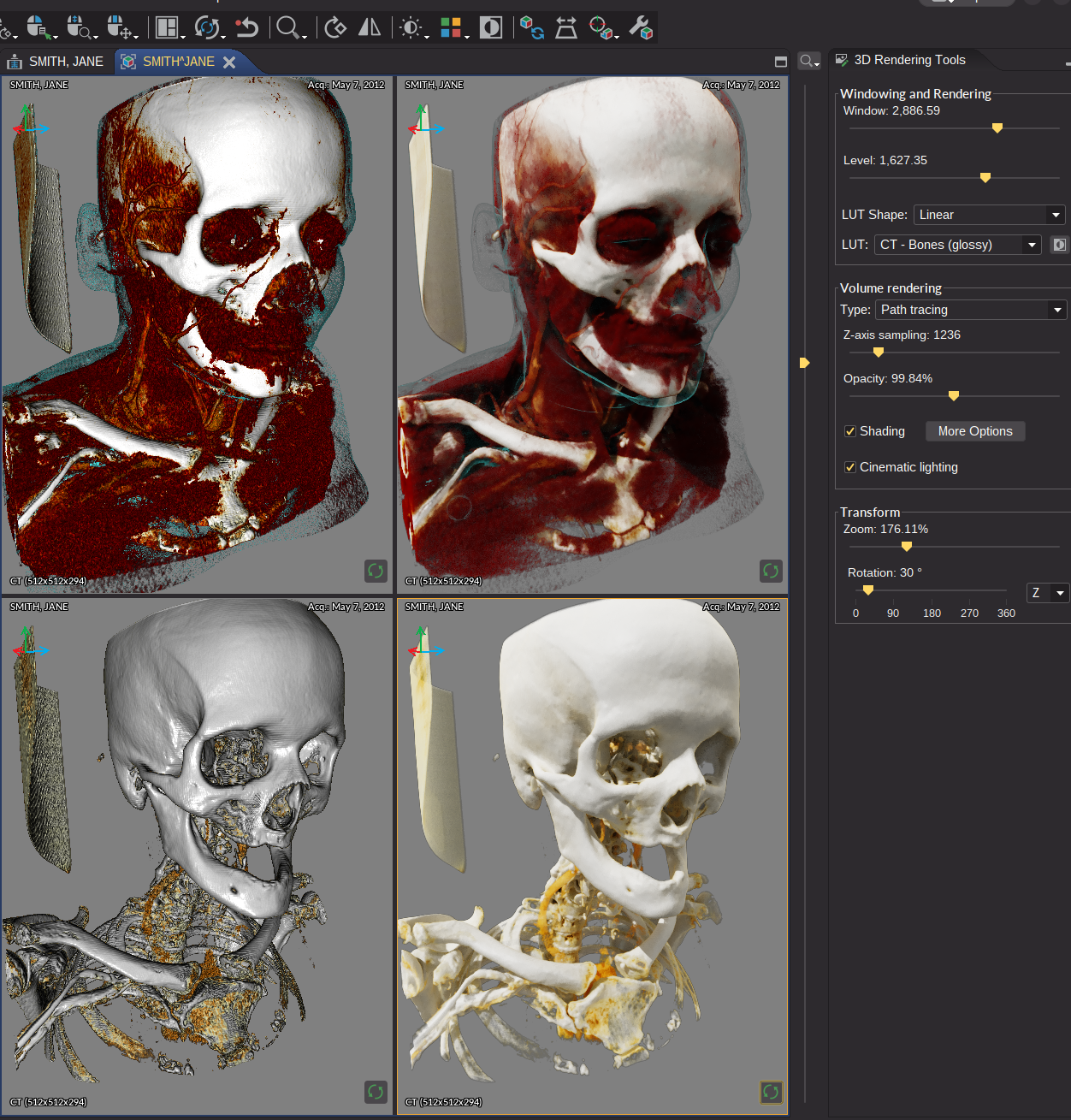
The same patient orientation axes as the MPR views are drawn in the 3D view since v4.7.0.
DICOM SEG segmentations linked to the series are rendered in the 3D viewer too — see Segmentation overlay in the 3D Volume Renderer.
Toolbar A
Actions in the toolbar:
- Reload volume — fully reloads the volume from the source series.
- Orthographic / Perspective projection — toggles between orthographic projection (parallel lines preserved, no foreshortening — useful for measurements) and perspective projection (depth cues, more natural-looking view). Perspective is the default.
- MPR Crosshair Cut — opens the cut mode to interactively clip the rendered volume along the anatomical planes defined by the MPR crosshair.
- 3D preferences — opens the Preferences.
Other toolbar buttons (LUT, reset, layout, synchronize…) are documented in the sections below. The Capture button since v4.8.0 saves the view as a picture, records it, or exports a turn of the volume as an animation with Export rotation — see Capture.
MPR Crosshair Cut Mode
The 3D viewer can display an MPR crosshair overlay since v4.7.0, synchronized with the MPR viewer and allowing you to clip the rendered volume along the anatomical planes defined by the crosshair position and orientation. The crosshair position and rotation stay synchronized in real time between the 2D MPR planes and the 3D rendering.
Recommended workflow
- Open the MPR viewer from a series view.
- In the MPR toolbar, click — this splits the current tab into a side-by-side layout with the MPR views on one side and the 3D volume rendering on the other.
- In the 3D view, activate a cut mode using the toolbar button or by right-clicking and selecting MPR Crosshair Cut.
Alternative workflow
Open the 3D viewer first, then activate a cut mode from the toolbar or the right-click menu. The MPR viewer opens automatically for the same series, but in a separate tab. To obtain the side-by-side layout, drag the MPR tab and dock it next to the 3D view using the docking handles.
Cut modes
- No cut — no clipping; the full volume is rendered.
- 18 directional modes — clip the volume in halves, quarters, or eighths relative to the MPR crosshair position, along each anatomical axis (Left / Right, Anterior / Posterior, Superior / Inferior).
The crosshair overlay uses the same LPS axis color coding as the MPR viewer.
3D View Synchronization
The 3D viewer can host multiple side-by-side views of the same volume and keep them coordinated since v4.7.0. Because every 3D view in the container shows the same volume, the auto-sync button is always visible. A single synchronization profile bundles a per-action toggle list with camera-level actions enabled by default and photometric / rendering actions left opt-in.
Toolbar “Synchronize” checkbox
The Synchronize checkbox in the toolbar drives the global on/off state for the 3D container. It defaults to ON. Toggling it propagates the new state to every per-view auto-sync button on the next refresh.
Per-view auto-sync button
When the layout has two or more views, a small auto-sync button appears in the bottom-right corner of each view. Its tint reflects the per-view state — red when sync is OFF for the view, green when ON. Clicking the button opens a popup with:
- Synchronize this view — master on/off toggle for auto-sync on this view (also mirrored into the toolbar Synchronize checkbox so the toolbar state always reflects the active view).
- Per-action toggles — independent checkboxes that decide which actions this view propagates to (and receives from) the other 3D views. The popup stays open while you flip several options.
- Apply to all views — copies this view’s effective per-action map to every other 3D view in the container. Unlike the 2D variant of this entry, no FoR filtering is applied because all 3D views share the same volume.
Right-click “Synchronize” submenu
The view’s right-click context menu also exposes a Synchronize submenu with the same per-action toggles and the same Apply to all views entry, useful when you want to adjust the sync map without first enabling/disabling the master toggle.
Per-action defaults
| Group | Action | Default |
|---|---|---|
| Camera | Pan | ON |
| Camera | Zoom | ON |
| Camera | Rotation (slider rotation + axis selection) | ON |
| Photometric | Window / Level | OFF |
| Photometric | Preset | OFF |
| Photometric | LUT Shape | OFF |
| Photometric | Invert LUT | OFF |
| Photometric | LUT | OFF |
| Rendering | Rendering Type | OFF |
| Rendering | Volume Opacity | OFF |
| Rendering | Volume Shading | OFF |
| Rendering | Cinematic lighting since v4.8.0 | OFF |
| Rendering | Orthographic projection | OFF |
| Rendering | MPR Crosshair Cut | OFF |
| Rendering | Segmentation type | OFF |
Camera-level actions are on by default because keeping multiple 3D views framed identically is the common workflow when comparing rendering types or LUT presets side by side. Photometric and rendering actions are opt-in because the typical reason to open a second 3D view is to diverge on those settings (e.g. one view in Composite with a soft-tissue LUT, the other in MIP).
The view you are actively interacting with always applies its own changes locally, even when the corresponding action is unchecked in its sync map. Only other views gate on the per-action toggle. This keeps sliders and mouse drags responsive while letting you decide which actions propagate to the rest of the container.
3D Rendering Tools
This tab groups every control that affects how the volume is rendered. To return to the original settings, click the toolbar button or pick Reset from the context menu.
Windowing and Rendering B
Some of the options below are also accessible from the toolbar and the right-click menu.
- Window — width of the voxel-value range mapped to the displayed value range.
- Level — center of the range defined by Window.
- LUT Shape — transfer function applied between input and display values: linear, sigmoid, or logarithmic. Default is linear.
-
LUT — a 3D Lookup Table that maps grayscale voxel values to color, opacity, and lighting for visualization. Picking a LUT from the toolbar or the right-click menu is usually easier: LUTs there are ordered by modality and shown with a preview. Custom LUTs can be created and modified with the Volume LUT Editor, and the whole library is described in Color Maps since v4.8.0. In the list since v4.8.0:
- Presets are grouped by anatomical category (bone, vascular, cardiac, lung and airways, soft tissue and skin…). The CT list includes the classic volume rendering presets of 3D Slicer (aorta, cardiac, coronary and pulmonary arteries, liver vasculature, muscle, soft tissue, airways…).
- MR presets are defined as a percentage of the volume maximum and PET presets in SUVbw (standardized uptake value), so they adapt to the loaded series instead of assuming a fixed intensity range.
- Presets you use often can be marked as favorites, which keeps them at the top of the list.
- Each preset carries one to three dots showing its rendering cost on the loaded volume — hover them to read Rendering cost: N % of the voxels visible — so an empty preset or a solid block is spotted before it is applied.
- Presets marked with a ✦ are the ones that suit Cinematic lighting and Path tracing best: bone, contrast-filled vessels, cardiac, skin and endoscopic views for CT, Angiography for MR and Fetal for ultrasound. Their opaque, well-separated materials give clean shadows and reflections.
- Invert LUT — flips the LUT direction.
Volume Rendering C
Controls for the rendering algorithm, quality, transparency, lighting, and shading.
- Type — defines the rendering algorithm applied to the volume:
- Composite — classic volume rendering. Each voxel contributes color and opacity along the ray, blended front-to-back to produce the final image.
- MIP Max — Maximum Intensity Projection. Keeps the highest-intensity voxel encountered along each ray. Useful for highlighting bright structures such as contrast-enhanced vessels or bones.
- MinIP — Minimum Intensity Projection. Keeps the lowest-intensity voxel along each ray. Useful for visualizing air-filled structures such as airways.
- MIP Mean — Mean Intensity Projection. Averages intensities along each ray, producing a smoother representation of the volume.
- Iso Surface — renders a 3D surface at a given intensity threshold, representing structures of a uniform density (e.g. bone segmentation).
- Path tracing since v4.8.0 — the most realistic look, close to a photograph. Weasis simulates how light travels: it scatters inside the tissue, bounces from one structure to another, casts soft shadows from the main light and comes from the chosen lighting Environment (see Cinematic lighting below). A built-in denoiser smooths the first, grainy frames, then the image refines itself over a few seconds while the view stands still; the progress is shown at the bottom of the view. Rotating or changing anything starts the refinement again, and while you drag, the view shows the faster Composite rendering with cinematic lighting instead. Choosing this type turns Cinematic lighting (and with it Shading) on. The same More Options controls apply (light direction, environment, exposure), and the Cinematic lighting quality preference sets how many times the light may bounce.
- Z-axis sampling — distance between successive samples along each ray. Smaller values capture more detail at the cost of compute time; the default is derived from the volume size.
- Opacity — global opacity factor for the voxels. Can be pushed above 100 % to compensate for the lower-than-100 % values defined by some Volume LUTs.
- Shading — enables shading on the rendered surface. The default is taken from the Volume LUT; the additional options let you override the inherited lighting settings. The toggle also lights the segmentation surfaces drawn over or in place of the anatomy since v4.7.3 — see Segmentation overlay in the 3D Volume Renderer.
- Cinematic lighting since v4.8.0 — a more realistic look for the Composite and Iso Surface types. A single main light casts shadows through the volume, and structures darken where they are enclosed or close to one another (ambient occlusion), which makes depth easier to read. Brightness is then adjusted like in a photograph, so bright areas fade smoothly instead of turning flat white. It refines the shading, so turning it on also turns Shading on. The same checkbox is available in the right-click menu of the view. The More Options button then gives, in addition to the shininess:
- Shadow strength and Ambient occlusion — how much each effect darkens the image (0 disables it). Both run from 0 to 1; the defaults are 0.70 and 0.60.
- Exposure — overall brightness of the image, from 0.25 to 3 (default 1.20).
- Light azimuth and Light elevation — where the main light comes from, relative to the viewer, each from −90° to 90°. Both at 0° give a headlight; the default (−30° azimuth, 35° elevation) lights the scene from the upper left, which reveals the shape of the anatomy best.
- Environment and Environment strength — soft light coming from all around the volume, as in a photo studio: Studio (neutral key, fill and rim panels, the default), Overcast (soft shadowless sky), Warm (low sun) or Cool (clinical overhead panels), or None to keep the flat ambient light of the LUT. The environment turns with the camera, fills the shadows with colored light and adds soft reflections whose blur follows the Shininess. The strength runs from 0 to 2 (default 1.0).
The screenshot at the top of the page shows the difference: the left column E uses plain Shading, the right column F Cinematic lighting on the same presets, and the selected view, bottom right, Path tracing.
Cinematic lighting takes roughly two to three times longer to render than plain shading, because every point of the volume also has to look toward the light and around itself. On a slow graphics card, lower the Cinematic lighting quality in the preferences or leave the option off: the shadows and occlusion follow the Dynamic quality setting while you rotate the view, so interaction stays smooth even at the higher quality levels.
Transform D
Zoom the volume and rotate it around one of the three patient axes:
- Zoom slider — scales the rendering.
- Rotation slider and axis selector — pick the Left / Right, Anterior / Posterior or Superior / Inferior axis (LPS coordinate system), then turn the volume around it. The slider sets the twist around that axis alone and leaves the tilt given by the mouse untouched, so a view can be spun around the patient’s vertical axis without losing its inclination since v4.8.0.
Volume LUT Editor
Custom Volume LUTs can be created and edited directly in the 3D viewer since v4.7.2. A Volume LUT (also called a preset) defines, for each voxel intensity, the color, the opacity, and the lighting coefficients used by the volume rendering.
Volume presets are edited in the color map editor, the same dialog that creates the color maps of the 2D viewer and of the fusion overlays — see Color Maps for the complete description. Open it from the LUT list in the toolbar
or in the right-click menu, with the **Edit color maps…** entry at the bottom of the list. The list of the dialog then opens on the **3D presets** of the modality of the loaded volume.What is specific to a volume preset:
- Volume preset, in the quick settings, is what makes a map usable by the 3D viewer: it gains lighting, and its positions are anchored to the values of the volume (Hounsfield units for CT, SUVbw for PET, a percentage of the maximum otherwise).
- Shade, Specular power and Edge emphasis set the default lighting of the preset, which can still be overridden afterward from the Volume Rendering panel.
- Each stop carries, besides its color and its opacity, the Ambient / Diffuse / Specular coefficients of its material. The Material list applies a ready-made combination (matte, soft tissue, skin, vessel, bone, glass, metal) to the selected stop or to all of them.
- The histogram of the loaded volume is drawn behind the opacity curve, and the status line reports the share of the voxels the preset leaves visible — a quick way to tell an empty preset from a solid block.
Your presets are saved with your other color maps in customColorMaps.json, in the Weasis preferences folder, on this workstation. Presets created with an earlier version, in customVolumePresets.json, are imported once on the first start.
Open the editor from the LUT list in the toolbar
or in the right-click menu: the **Edit Volume LUT…** entry is located at the bottom of the list.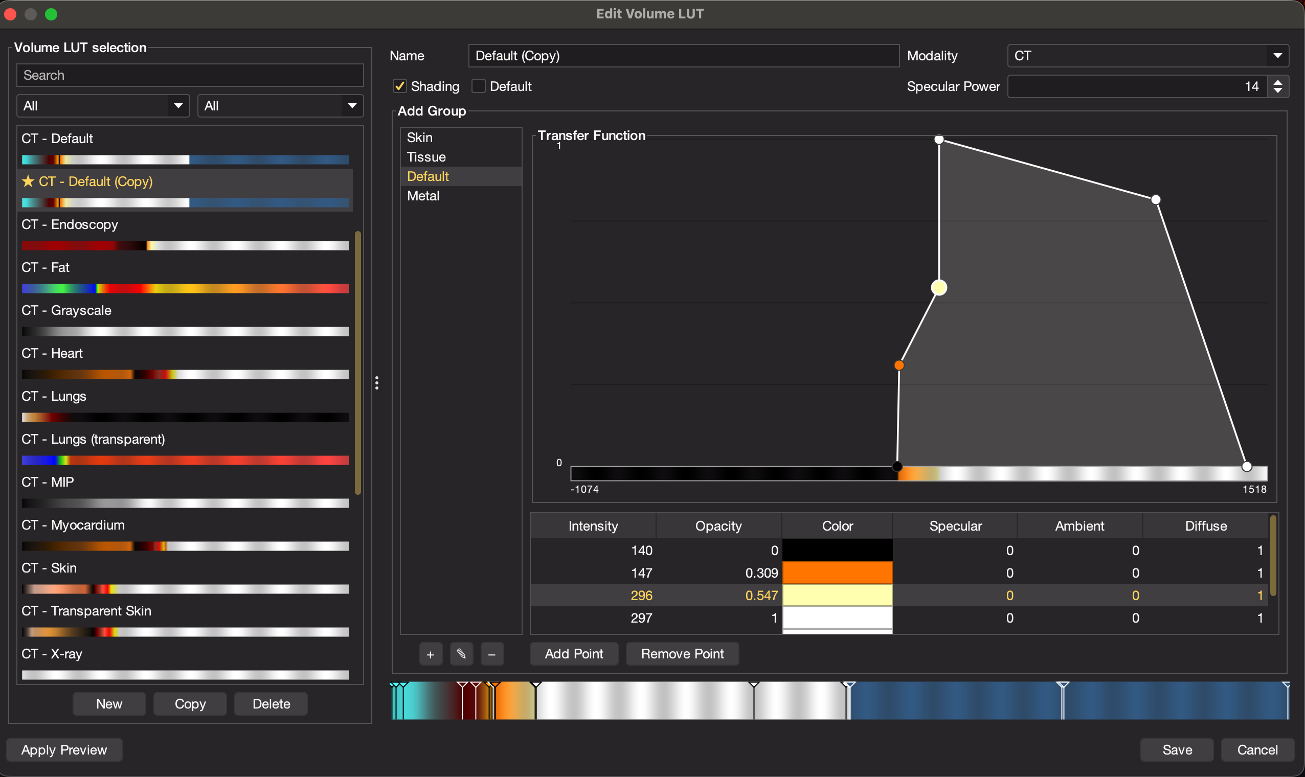
Preset list A — the left side of the dialog lists all the available presets. A search field and two filters (modality and All / Editable / Built-in) help to locate a preset in a long list.
Built-in presets cannot be modified. Use the buttons below the list to create an editable one:
- New — creates an empty custom preset.
- Copy — duplicates the selected preset. Copying a built-in preset is the easiest way to start from a working configuration and adjust it.
- Delete — removes the selected custom preset (with confirmation).
Preset properties B:
- Name — the name displayed in the LUT lists (required).
- Modality — the modality group under which the preset is listed (e.g. CT, MR, PET). Choose Default to make it available for all modalities.
- Default — makes this preset the one selected automatically when a volume of that modality is opened.
- Shading and Specular Power — default lighting behavior of the preset, which can still be overridden afterward from the Volume Rendering panel.
Transfer function C — a preset contains one or more groups, and each group is a list of points placed along the voxel-intensity axis. Every point defines an opacity, a color, and the Ambient / Diffuse / Specular lighting coefficients; values between two points are interpolated linearly.
The points of the selected group can be edited in two ways:
- Graphically, in the transfer-function graph: double-click on the curve to add a point, drag a point to change its intensity and opacity, double-click a point to pick its color, and press Delete to remove the selected point.
- Numerically, in the point table (Intensity, Opacity, Color, Specular, Ambient, Diffuse columns), together with the Add Point / Remove Point buttons.
The resulting color bar is previewed under the graph, and every change is also applied live to the current 3D view after a short delay (the Apply Preview button forces an immediate update).
- Save — validates and persists the preset, then closes the dialog.
- Cancel — discards the unsaved changes and restores the LUT that was active before opening the editor.
Custom presets are stored in the customVolumePresets.json file inside the Weasis preferences directory, on this workstation.
Preferences
From the menu File > Preferences > Viewer > 3D Viewer.
OpenGL Support
Information about the graphics card and OpenGL capabilities, see Requirements.
3D Viewer
- Default layout — preferred layout used when opening the 3D viewer. Available layouts: 1×1 (single view, default), 1×2, 2×1, 1×3, 2×2.
- Max 3D texture size — maximum volume dimensions, both in X / Y (image width and height) and in Z (number of images in the stack composing the volume).
The maximum 3D texture defaults come from the graphics card. Lowering them (e.g. to 512) can produce a more fluid rendering on hardware that struggles with the full-size texture.
Volume Rendering
- Dynamic quality — reduces the rendering quality along the Z axis while you rotate or modify the view, for a smoother interaction. At the maximum slider position there is no quality reduction. The same reduction applies to the shadow and occlusion probes of the Cinematic lighting.
- Cinematic lighting quality since v4.8.0 — how finely the shadow and occlusion probes of the Cinematic lighting sample the volume, and how many bounces the Path tracing type follows: Low, Medium (default) or High. Higher levels give smoother shadows and richer indirect light at a higher rendering cost.
The FBO fragment-shader backend (OpenGL 3.3 – 4.2, and therefore always on macOS — see Requirements) additionally lowers the rendering resolution while the camera is being dragged since v4.7.3: the volume is ray-cast at the logical window resolution instead of the physical one and the result is upscaled for the duration of the gesture, which on a HiDPI / Retina display is a quarter of the pixels to compute. The frame drawn as soon as you release the mouse is at full resolution again. This is automatic and is independent of the Dynamic quality slider, which acts on the sampling along the ray; the Compute Shader backend (OpenGL 4.3+) always renders at full resolution.
- Default orientation — preferred starting orientation. Default: anterior view rotated 15° to the right and 15° downward.
- Background color — background color of the rendered scene.
- Light color — color of the light used to illuminate the rendering.
Video tutorials
Display an MR angiography series as a volume rendering, then switch to a MIP projection or pick a 3D LUT and adjust the window / level values: