MPR Viewer
Multi-planar reconstruction (MPR)
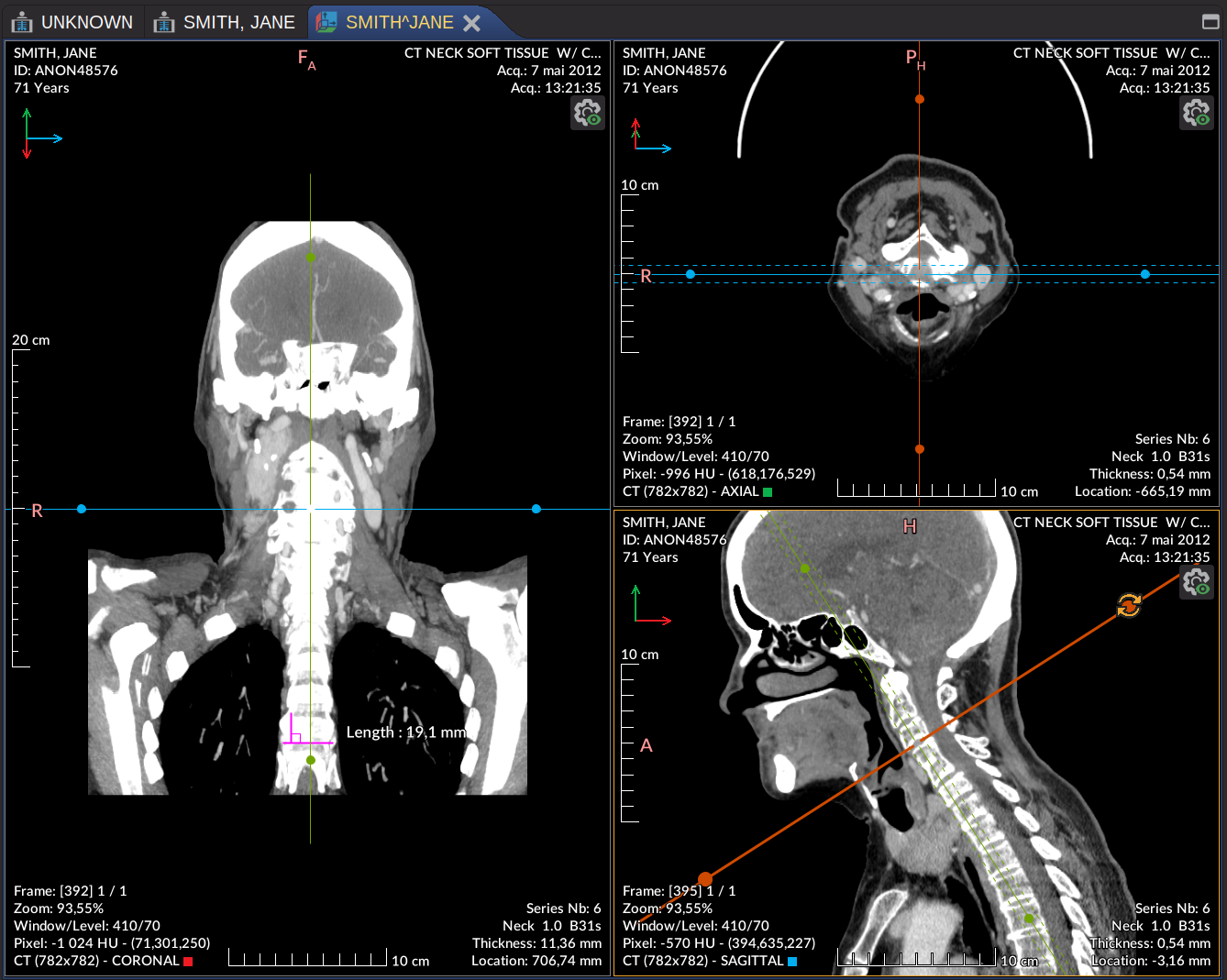
The MPR viewer reconstructs the two complementary anatomical planes from a volumetric acquisition: starting from the original plane (typically axial), Weasis computes the corresponding coronal and sagittal views, all kept in sync through a shared 3D crosshair. Oblique planes are also supported, since Version4.6.0.
The MPR view inherits most of the properties and actions of the DICOM 2D viewer, with one structural difference: the crosshair tool stays active regardless of which mouse action is selected. Open the MPR viewer from the icon in the toolbar, or by right-clicking a thumbnail in the DICOM Explorer.
Note
The menu and toolbar entries are only enabled when the series contains at least 5 images.
Tip
Opening MPR from a fused 2D view (PET/CT) carries the overlay over to the three planes — see Fusion in the MPR viewer.
Tip
If the series is a multi-phase 4D acquisition (e.g. a cardiac CT with several temporal phases), Weasis automatically splits it into individual phase sub-series when 2–7 phases are detected. For series with 8 or more phases, a confirmation dialog is shown first. Open any resulting phase sub-series to reconstruct it in the MPR viewer — see 4D Series Sub-Series Splitting.
Note
To reconstruct the volume along a curve instead of a flat plane — for example a dental panoramic from a CBCT — draw a polyline and use the Curved MPR actions. See Curved MPR Viewer.
Crosshair actions
The crosshair stays synchronized across the three MPR planes (and with any other FoR-coupled view). Three actions are available on its handles:
- Move — translate the cursor in 3D space by dragging the center of the crosshair.
- Move axis — slide the crosshair along one axis by selecting and dragging that line.
- Rotate — rotate the crosshair around its center by dragging one of the end points along the axes.
Synchronization between MPR planes
The MPR viewer uses different sync defaults from the 2D viewer: in addition to the structural crosshair coupling, Scroll, Zoom, and Window / Level are ON by default between the three planes. The remaining per-action propagations (Pan, Rotation, Flip, Spatial unit) are off by default and can be enabled explicitly. The options live in two places:
- The global Synchronize drop-down popup (next to the layout button) — master on/off plus per-action toggles for the whole container.
- The Synchronize submenu in each MPR view’s settings popup — for per-view fine-tuning.
See View Synchronization in MPR for the full mechanics.
The MPR views can be reorganized into different layouts via the layout button.
View settings
Open the per-view settings popup with the icon in the top-right corner of any MPR view:
- Center — recenter the crosshair in the view.
- Show Center of Crosshair — show or hide the center point.
- Show Crosshair — show or hide the crosshair lines. When hidden, the crosshair actions are inactive.
- MIP Thickness — slab thickness for the active MIP projection, expressed in slices in the cross-axis direction. Can also be adjusted with Alt + mouse scroll on an axis. Note: the projection may take a moment to refresh, since MIP in MPR is computed in the background and does not use 3D acceleration.
- MIP Type — projection mode applied to the slab:
- None — no MIP applied.
- Min — Minimum intensity projection.
- Mean — Mean intensity projection.
- Max — Maximum intensity projection.
- Build a new series from the current view / Build three series from MPR views — save the reconstructed MPR slices back as new DICOM series (since Version4.7.0). The first option exports the current plane only; the second (in the All views submenu) exports the three planes, each as a separate series. Background borders are cropped uniformly across every slice so the exported series keeps a constant image size. The crosshair is restored to its initial position when the build completes.
- Synchronize — per-view sync options: independent toggles for Scroll, Pan, Zoom, Rotation, Flip, Window / Level, Spatial unit, plus an Apply to all views entry that propagates the current selection to every other MPR view (see View Synchronization in MPR).
Note
Most MPR settings are also reachable via keyboard shortcuts — see the MPR shortcuts.
Try it on a volume dataset
Crosshair line colors
Each crosshair line represents the intersection of one of the other two planes with the current view. The line color identifies which plane it belongs to:
| Color | Plane | Anatomical axis | Visible in |
|---|---|---|---|
| Red | Coronal | Anterior → Posterior | Axial, Sagittal |
| Green | Axial | Inferior → Superior | Coronal, Sagittal |
| Blue | Sagittal | Right → Left | Axial, Coronal |
For oblique planes, line colors blend proportionally based on the contribution of the primary axes.
Orientation axes
The patient orientation axes are drawn in the top-left corner of each MPR view, indicating how the current slice is oriented in 3D space:
| Color | Direction |
|---|---|
| Red arrow | Anterior → Posterior |
| Green arrow | Inferior → Superior |
| Blue arrow | Right → Left |
See Orientation in multiplanar reconstruction (MPR) for the wider orientation-labeling conventions.
The same axes widget is also drawn in the 3D viewer since Version4.7.0.
Volume geometry handling
Since Version4.7.0, when Weasis detects that a volume cannot be reconstructed as a perfect rectilinear grid, a confirmation dialog appears before the MPR views are built. The conditions are evaluated in this priority order — only the first match triggers the dialog:
| Condition | Dialog message |
|---|---|
| Slices are not parallel | Slice orientations are not parallel! |
| Slice spacing is irregular | Space between slices is not regular! |
| Too few slices for the gantry tilt | There are too few slices compared to the geometric deformation! |
In each case the message ends with:
The images may be displayed incorrectly. Do you want to rectify the images anyway?
Dialog choices
- Yes — Rectify geometry — re-slices the volume to align it with the patient’s anatomical orientation. Ensures correct spatial proportions for measurements and ratios across planes, at the cost of one interpolation pass that may slightly soften the image.
- No — Stack images — stacks the original images directly, with no geometric correction. Preserves the full original image quality and avoids interpolation, but distances, ratios, and measurements may not reflect true anatomical values.
Tip
Pick Yes when accurate measurements matter. Pick No when image quality and the absence of interpolation artifacts take precedence.
Status indicator
A persistent red label is then shown in the bottom-left corner of every MPR view to indicate the active mode:
| Choice | Bottom-left indicator |
|---|---|
| Yes (rectify) | Geometry aligned to patient orientation |
| No (stack) | Patient geometry correction skipped — spatial accuracy may be reduced |
Preferences
From the main menu File > Preferences > Viewer > MPR (since Version4.1.0):
- Auto center axes — how the crosshair is recentered when it moves out of the visible area. Always recenters after every move; the default option only recenters when the position is almost no longer visible.
- Crosshair gap at the center — size of the empty space drawn around the cursor point, so the marker does not occlude the structure being inspected.
- Default layout — preferred layout used when opening the MPR viewer.